Sharp XV-Z1A Manuel de service
Naviguer en ligne ou télécharger Manuel de service pour Projecteurs Sharp XV-Z1A. Sharp XV-Z1A Service manual Manuel d'utilisatio
- Page / 65
- Table des matières
- MARQUE LIVRES

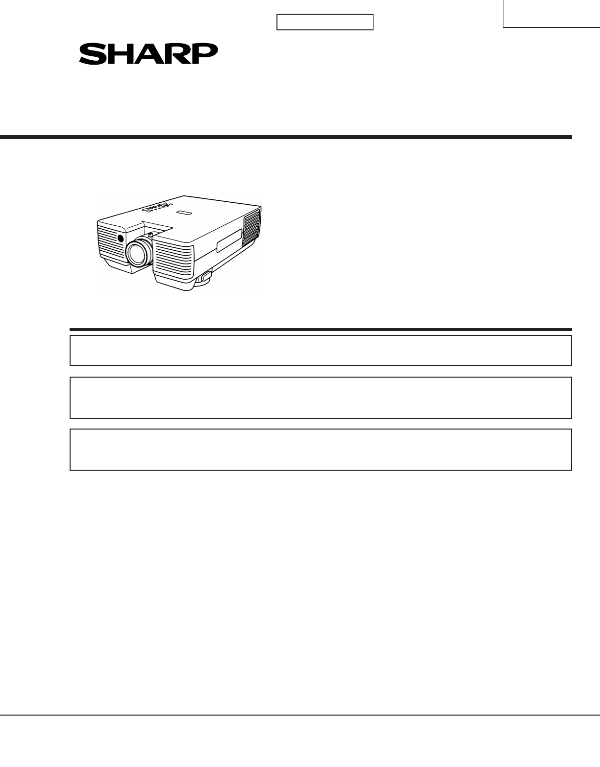
- XV-Z1E/A 1
- CONTENTS 2
- NOTE TO SERVICE PERSONNEL 3
- Specifications 4
- Location of Controls 6
- Demensions 8
- REMOVING OF MAJOR PARTS 9
- 4. Removing the PWBs 12
- TOTAL TIME 14
- (located above the AC inlet) 15
- THE OPTICAL UNIT OUTLINE 16
- TOP VIEW 18
- SIDE VIEW 18
- Adjustment directions 19
- Replacing the LCDs 20
- ELECTRICAL ADJUSTMENT 21
- Adjustment Position 22
- Checking the PWB performance 29
- (Continued) 30
- Checking synchronization 36
- Checking the PLL circuit 36
- No image 38
- Lamp failure to light up 41
- No sound 42
- Ref. No.17 43
- SAFETY NOTES: 46
- IMPORTANT SAFETY NOTICE: 46
- SICHERHEITSANMERKUNGEN: 46
- TO THEAMISTOR 47
- SIGNAL UNIT 48
- TO SIGNAL 49
- CTANZ0712CE01 58
- RDENC0228CEZB 60
- RDENC0228CEZA 60
- RDENC0228CEZC 61
- RDENC0228CEZD 61
- (XV-Z1A) 62
- PARTS LIST 65
- ERSATZTEILLISTE 65
Résumé du contenu
1XV-Z1E/ASHARP CORPORATIONSERVICE MANUALSERVICE-ANLEITUNGPAL/SECAM/NTSC SYSTEMLCD PROJECTORLCD PROJEKTORIm lnteresse der Benutzersicherheit (erforderl
XV-Z1E/A102. Removing the front cabinets2-1. Tilt the front-right cabinet forward. Pull it up out of position.2-2. Tilt the front-left cabinet forwar
XV-Z1E/A113. Removing the rear cabinet and video terminal cover3-1. Remove the two screws off the rear cabinet and the screw from the static ground le
XV-Z1E/A124. Removing the PWBs4-1. Remove the two screws that fix the PC terminal cover to the bottom cabinet.4-2. Remove the two screws off the outpu
XV-Z1E/A135. Removing the optics mechanism assembly5-1. Remove the two screws off the angles A and B of the carrying handle. Detach the carrying hand
XV-Z1E/A14CONTROLLING THE TOTAL OPERATING HOURS OF THE LAMPThe following control is carried out when the lamp has been used for 1900 hours and 2000hou
XV-Z1E/A15RESETTING THE LAMP OPERATING HOUR COUNTERThe unit is designed to keep its power off when the lamp has been used for 1900 and 2000hours. This
XV-Z1E/A16B-LCDG-LCD R-FilterGREENBLUEBLUEREDR-LCDPolarizer filmDichroic coating(B transmission)Dichroic coating(B reflection)Incident polarizer plate
XV-Z1E/A17)()(CONVERGENCE AND FOCUS ADJUSTMENT» Start the convergence and focus adjustments with the top cabinet and the signal shieldremoved but the
XV-Z1E/A18XZθYXYθZXYθZXZθYNotch and hole "a"(Use an eccentricscrewdriver.)Notch and hole "b"(Use an eccentricscrewdriver.)Lock scr
XV-Z1E/A19X direction LCD right and leftConvergence Y direction LCD top and bottomθZ direction Rotation around Z axis LCD turning axisZ direction LCD
2XV-Z1E/A• CHASSIS LAYOUT ... 123• BLOCK DIAGRAM ...125• OVERALL WIRING DI
XV-Z1E/A20Replacing the LCDsWith the top cabinet removed(1) Remove the output shield.(2) Disconnect the LCD flat cable from the output PWB connector.(
XV-Z1E/A21ELECTRICAL ADJUSTMENTNOTE : The settings have been factory-adjusted to their best points. If any of them gets out of spec or afterany releva
XV-Z1E/A22StepAdjustment PositionAdjustment Conditions Adjustment Method7 Contrast(DAC)1. Receive the 10 step grayscale signal of NTSC.2. Connect the
XV-Z1E/A23StepAdjustment PositionAdjustment Conditions Adjustment Method11 D/A Output level(NTSC) (DAC)1. Receive the 10 step grayscale signal of NTSC
XV-Z1E/A24StepAdjustment PositionAdjustment Conditions Adjustment Method15 Gain(DAC)1. Receive the 10 step grayscale signal of NTSC.2. Connect the osc
XV-Z1E/A25StepAdjustment PositionAdjustment Conditions Adjustment Method17 Gamma(DAC)1. Receive the 10 step grayscale signal of NTSC.2. Connect the os
XV-Z1E/A26StepAdjustment PositionAdjustment Conditions Adjustment Method20 TINT ofcomponent(DAC)1. Receive the colour barsugnal for component ter-mina
XV-Z1E/A27StepAdjustment PositionAdjustment Conditions Adjustment Method24 COLOUR ofcomponent(DAC)1. Receive the colour bar sig-nal of NTSC.2. Connect
XV-Z1E/A28StepAdjustment PositionAdjustment Conditions Adjustment Method29 Vertical position(PAL)1. Receive the monoscopesignal of PAL.2. Push S2001 a
TROUBLE SHOOTING TABLE (Continued)29XV-Z1E/AChecking the PWB performanceUse specified cable.NoNoNoNoNoNoNoNoYesYesYesYesYesYesYesYesYesRGB input in tr
3XV-Z1E/A12LampReflectorNOTE TO SERVICE PERSONNELUV-RADIATION PRECAUTIONThe light source, metal halide lamp, in the LCDprojector emits small amounts
TROUBLE SHOOTING TABLE (Continued)30XV-Z1E/AYes Checking the G signal line of signal PWBNoNoYesNoNoNoNoNoYesYesYesYesYesNoYesYesYesNoNoYesNoYesNoNoNoN
TROUBLE SHOOTING TABLE (Continued)31XV-Z1E/AYesChecking the R signal line of signal PWBNoNoYesNoNoNoNoNoYesYesYesYesYesNoYesYesYesNoNoYesNoYesNoNoNoNo
TROUBLE SHOOTING TABLE (Continued)32XV-Z1E/AYesChecking the B signal line of signal PWBNoNoYesNoNoNoNoNoYesYesYesYesYesNoYesYesYesNoNoYesNoYesNoNoNoNo
TROUBLE SHOOTING TABLE (Continued)33XV-Z1E/AChecking the G signal line of output PWBNoYesConnector CC poorly soldered or in trouble.Are outputs at pin
TROUBLE SHOOTING TABLE (Continued)34XV-Z1E/AChecking the R signal line of output PWBNoYesConnector CC poorly soldered or in trouble.Are outputs at pin
TROUBLE SHOOTING TABLE (Continued)35XV-Z1E/AChecking the B signal line of output PWBNoYesConnector CC poorly soldered or in trouble.Are outputs at pin
TROUBLE SHOOTING TABLE (Continued)36XV-Z1E/AChecking synchronizationNoNoYesYesYesNoAre there signal outputs at pins (3)(IN+) of IC2003 and IC2004?Are
TROUBLE SHOOTING TABLE (Continued)37XV-Z1E/AChecking the remote control circuitYesNoIC5001, IC5101, IC5102 or nearby circuit in trouble.Press the MENU
TROUBLE SHOOTING TABLE (Continued)38XV-Z1E/ANo imageYesIs lamp on?YesNoIs voltage aplied to connector EA?Refer to the troubleshooting of the lamp/ball
TROUBLE SHOOTING TABLE (Continued)39XV-Z1E/ANo colour or unusual tint with NTSC signal NoYesIC5001 or nearby circuit in trouble.IC1201, IC1206 or near
4XV-Z1E/ASpecifications
TROUBLE SHOOTING TABLE (Continued)40XV-Z1E/AYesYesNo synchronizationNoYesYesNoNoNoCheck the signal line from IC6005.Is there video signal input at pin
TROUBLE SHOOTING TABLE (Continued)41XV-Z1E/ALamp failure to light upNoNoYesYesYesReplace TGU1701. Check connectors.Is discharge noise heard?NoYesRepla
TROUBLE SHOOTING TABLE (Continued)42XV-Z1E/ANo soundYesNoCheck IC302 and its peripheral circuits.YesNoDoes voltage at pin (9) of IC301 change with VOL
XV-Z1E/A XV-Z1E/AHGFEDCBA123456789101112CHASSIS LAYOUT / CHASSIS-ANORDNUNGRef. No.17**POWER/BALLAST UNIT–CREDENC0228CEZCREDENC0240CEZCPOWER/BALLAST UN
XV-Z1E/A XV-Z1E/AHGFEDCBA123456789101112BLOCK DIAGRAM / BLOCKSCHALTBILD125 126
XV-Z1E/A XV-Z1E/AHGFEDCBA123456789101112OVERALL WIRING DIAGRAM / GESAMTSCHALTPLAN127 128XV-Z1EXV-Z1A
XV-Z1E/A XV-Z1E/AHGFEDCBA123456789101112SC6001H: 10µsec/divV: 500mV/div1SC6001H: 10µsec/divV: 500mV/div2VOLTAGE MEASUREMENT CONDITION:1. Voltages at t
XV-Z1E/A XV-Z1E/AHGFEDCBA123456789101112141 142OUTPUT UNIT-1/5 / AUSGABEEINHEIT-1/5SIGNALTO THEAMISTOR
XV-Z1E/A XV-Z1E/AHGFEDCBA123456789101112143 144OUTPUT UNIT-2/5 / AUSGABEEINHEIT-2/5SIGNAL UNIT
XV-Z1E/A XV-Z1E/AHGFEDCBA123456789101112145 146OUTPUT UNIT-3/5 / AUSGABEEINHEIT-3/512345678910 11 1213141516171819202122232412345678910 11 12131415161
5XV-Z1E/ASpecifications
XV-Z1E/A XV-Z1E/AHGFEDCBA123456789101112147 148OUTPUT UNIT-4/5 / AUSGABEEINHEIT-4/5
XV-Z1E/A XV-Z1E/AHGFEDCBA123456789101112149 150OUTPUT UNIT-5/5 / AUSGABEEINHEIT-5/5
XV-Z1E/A XV-Z1E/AHGFEDCBA123456789101112151 152OUTPUT SUB UNIT / AUSGABE-NEBENEINHEITTO R/C
XV-Z1E/A XV-Z1E/AHGFEDCBA123456789101112SIGNAL UNIT-1/5 / SIGNALEINHEIT-1/5131 132
XV-Z1E/A XV-Z1E/AHGFEDCBA123456789101112SIGNAL UNIT-2/5 / SIGNALEINHEIT-2/5133 134
XV-Z1E/A XV-Z1E/AHGFEDCBA123456789101112SIGNAL UNIT-3/5 / SIGNALEINHEIT-3/5135 136
XV-Z1E/A XV-Z1E/AHGFEDCBA123456789101112SIGNAL UNIT-4/5 / SIGNALEINHEIT-4/5137 138
XV-Z1E/A XV-Z1E/AHGFEDCBA123456789101112SIGNAL UNIT-5/5 / SIGNALEINHEIT-5/5139 140
XV-Z1E/A XV-Z1E/AHGFEDCBA123456789101112153 154VIDEO INPUT UNIT-1/2 / VIDEOEINGANGSEINHEIT-1/2CTANZ0712CE01
XV-Z1E/A XV-Z1E/AHGFEDCBA123456789101112155 156VIDEO INPUT UNIT-2/2 / VIDEOEINGANGSEINHEIT-2/2CTANZ0712CE01
6XV-Z1E/ALocation of Controls
XV-Z1E/A XV-Z1E/AHGFEDCBA1 23456HGFEDCBA123456157 158POWER/BALLAST UNIT-A / NETZ-/BALLASTEINHEIT A(XV-Z1E)POWER/BALLAST UNIT-B / NETZ-/BALLASTEINHEIT
XV-Z1E/A XV-Z1E/AHGFEDCBA1 23456HGFEDCBA123456159 160POWER/BALLAST UNIT-C / NETZ-/BALLASTEINHEIT C(XV-Z1E)POWER/BALLAST UNIT-D / NETZ-/BALLASTEINHEIT
XV-Z1E/A XV-Z1E/AHGFEDCBA1 23456HGFEDCBA123456161 162POWER/BALLAST UNIT-A / NETZ-/BALLASTEINHEIT A(XV-Z1A)POWER/BALLAST UNIT-B / NETZ-/BALLASTEINHEIT
XV-Z1E/A XV-Z1E/AHGFEDCBA1 23456HGFEDCBA123456163 164POWER/BALLAST UNIT-C / NETZ-/BALLASTEINHEIT C(XV-Z1A)POWER/BALLAST UNIT-D / NETZ-/BALLASTEINHEIT
XV-Z1E/A XV-Z1E/AHGFEDCBA1 23456HGFEDCBA123456IN INFRARED R/C RECEIVER UNIT / INFRAROT-EMPFÄNGEREINHEIT OPERATION KEY UNIT / BEDIENUNGSTASTENEINHEIT16
XV-Z1E/A XV-Z1E/AHGFEDCBA123456789101112177 178Ref. No. Part No. ★ Description Code Ref. No. Part No. ★ Description Code Ref. No. Part No. ★ Descripti
7XV-Z1E/AOperating the Wireless Mouse Remote Control
8XV-Z1E/ADemensions[Units: mm]
XV-Z1E/A9 Before starting this job, detach the lamp cage unit and the filter cover.1. Removing the top cabinet1-1. Remove the three screws at the
Plus de documents pour Projecteurs Sharp XV-Z1A

Produits connexes et manuels pour Projecteurs Sharp XV-Z1A
 (97 pages)
(44 pages)
(97 pages)
(44 pages)
 (140 pages)
(124 pages)
(137 pages)
(27 pages)
(140 pages)
(124 pages)
(137 pages)
(27 pages)
 (71 pages) (110 pages)
 (24 pages)
© 2020, manymanuals.fr. Tous droits réservés | 0.020 s |
 Manymanuals.com
 Manymanuals.de
 Manymanuals.fr
 Manymanuals.it
 Manymanuals.pl
 Manymanuals.cz
 Manymanuals.es
 Manymanuals-pt.com
Commentaires sur ces manuels